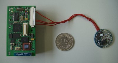
picture of the BTnodeRFID reader

|
| picture of the BTnodeRFID reader |
This site has three major parts. The first part describes the hardware components of the BTnodeRFID reader with assembly instructions. The next part specifies its power consumption. The last part shows a packaging of the BTnodeRFID reader suitable for mobile phones.
The BTnodeRFID reader consists mainly of two components: the BTnode and the SkyeModule M1-mini. The BTnode contains a microcontroller and a Bluetooth module. The M1-mini is responsible for RFID communication. The intercommunication between BTnode and M1-mini goings over a cable, connected to the serial ports. Additionally a subsection specifies the power consumption of the BTnodeRFID reader.
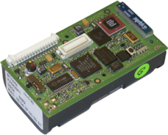
The BTnode is an autonomous wireless communication and computing platform based on a Bluetooth radio and a microcontroller. It serves as a demonstration platform for research in mobile and ad-hoc connected networks and distributed sensor networks. The operating system for the BTnode is freely available as Open-Source delivered with a couple of applications. For the hardware schema, assembly etc. is provided with public access.
|
| picture of the BTnode |
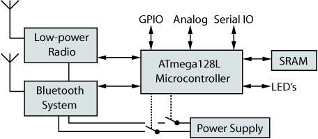 |
| component schema of the BTnode |
More information can be found in the extensive maintained BTnode-Wiki http://www.btnode.ethz.ch.
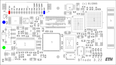
The BTnode has two supply options: a standard power supply with a input range 0.5-3.3 V DC (shipped and wired with the 2-cell AA battery case), alternatively a power supply with a input range between 3.6-5.0 V DC (can wired over the external connectors). If both supplies are powered, the alternate supply will be loaded.
|
| assembly top view of the BTnode, supply pins are color-marked |
If the power supply is within range 0.5-3.3 V, use pins N/GND and P, if power supply is within range 3.6-5.0 V, use pins GND/N and VDC_IN.
|
| picture of the RFID reader M1-mini |
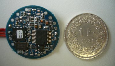
The SkyeModule M1-mini is a small multi-protocol RFID read/write module produced from SkyeTek. The ultra low profile (2.8 mm), the tiny footprint and the low power consumption (50 µA sleep, 15 mA idle, 40 mA scanning) of the M1-mini is a suitable candidate for space constrained, power sensitive applications.
There is a webpage http://www.skyetek.com/?tabid=84, a datasheet SkyeModule-M1-mini-Datasheet.pdf and a detailed reference guide SkyeModule-M1-mini-Reference-Guide.pdf about the M1-mini. The reader supports identify, read and write of following ISO tags, EPC tags and smart labels (passive tags at 13.56 MHz):
| Tag-It HF-I | ICode SLI | my-d |
| LRI512 | Tag-It HF | ICode 1 |
| PicoTag | GemWave | Mifare |
A detailed description about supported tags can be found in pdf reference on page 17.
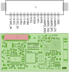
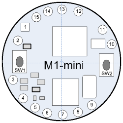
The M1-mini offers multiple host communication options: TTL, SPI and I2C. In context with the BTnode the TTL option is used, but the other options are also possible. A connection description between BTnode and M1-mini for the TTL option follows:
| BTnode | M1-mini |
 |
 |
| Interconnections between BTnode and M1-mini (TTL option) |
|
| BTnode | M1-mini |
|---|---|
| 1 (GND) | 13 (GND) |
| 4 (UART0_TXD) | 7 (RX_TTL) |
| 5 (UART0_RXD) | 6 (TX_TTL) |
| 13 (VCC_IO) | 12 (Vin) |
The internal antenna is enabled when shipped. If an external antenna is used, then a modification on M1-mini is needed. The external antenna is connected to pins 1 (GND) and 2 (ANT) on M1-mini.
The M1-mini offers multiple antenna connection options. It has an integrated internal antenna with a short range. But there is the option to connect an external antenna to reach higher ranges. We offer a self-written guide skyetek-antenna-design.pdf to design and use an external antenna on M1-mini. Alternatively the design guide SkyeRead-M1-Antenna-Design-Guide.pdf from SkyeTek can be useful.
We recommend to use calculations in the guide as a rough estimation. In the special case that the wire between coil/antenna and connector is too short, the calculations are useless. The best plan would be a trial and error method to try and prove the matching of the capacities.
The BTnode only powers the M1-mini if a Bluetooth connection is established. So we can seperate three power-states: unconnected, connected and maximum (tag identify requests at high rate):
| unconnected | connected | maximum |
|---|---|---|
| 45 mA | 60 mA | 70 mA |
| 20 h | 15 h | 12.85 h |
| comparison of current consumption and lifetime between power-states |
||
This measurements are done with a external power supply at 3.6 V. The lifetime is calculated on a mobile phone battery with a common current capacity of 900 mAh.
 |
 |
 |
| some photos from the first prototype |
||
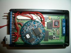
The packaging contains a BTnodeRFID reader, an external antenna, a power switch and a cable for the power supply, which can be connected to the mobile phone battery. The assembly instruction (for the nokia 6680 and possibly others) will coming soon, so stay tuned...